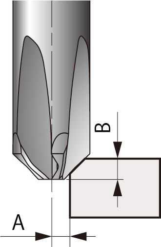
Chamfer Size Adjustment Chart
Create the machining program by referring to Offsets A and B in the table below for desired chamfer size.
This ensures Dc (Chamfer Alignment Diameter) and the Chamfer Center Point are aligned properly.

Formula for calculating Offsets A and B
A=(Dc-C)/2
B=(APMX+C)/2
*C=chamfer size
XC-C-03-M / N
| Chamfer size (mm) | Offsets (mm) | |
| A | B | |
| C0.3 | 0.85 | 0.65 |
| C0.4 | 0.80 | 0.70 |
| C0.5 | 0.75 | 0.75 |
| C0.6 | 0.70 | 0.80 |
XC-C-06-M / N
| Chamfer size (mm) | Offsets (mm) | |
| A | B | |
| C0.7 | 1.65 | 1.35 |
| C0.8 | 1.60 | 1.40 |
| C0.9 | 1.55 | 1.45 |
| C1.0 | 1.50 | 1.50 |
| C1.1 | 1.45 | 1.55 |
| C1.2 | 1.40 | 1.60 |
| C1.3 | 1.35 | 1.65 |
| C1.4 | 1.30 | 1.70 |
| C1.5 | 1.25 | 1.75 |
