How to Implement XEBEC Deburring Tool Path (XZY Turn-Mill Machines)
This section offers an example of implementing XEBEC Deburring Tool Path into the machining program.
G-codes and all other details are based on MELDAS controls. Make sure to use appropriate codes for your machine tool.
Machining Operations
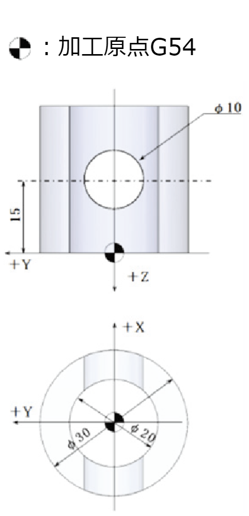
- Workpiece Shape
Outer Diameter Φ30mm x Inner Diameter Φ20mm - Previous Operation
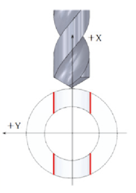
Drilled a Φ10mm hole that crosses orthogonally and on-center with the centerline of the workpiece - Target Edge to be Deburred
Upper and Lower edges of the inner diameter at the intersection of the Φ10 hole and the Φ20 hole
[Workpiece]

OP 1: Drilling

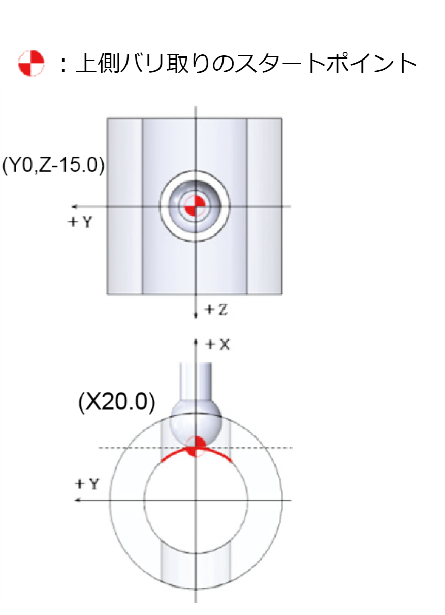
OP 2: Deburring Upper Edge

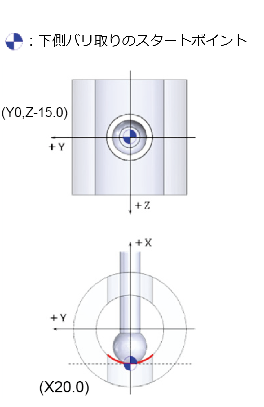
OP 3: Deburring Lower Edge

Program Overview
Main Program |
|
|---|---|
| O0001 (MAIN PROG); | |
| G0G18; | Select XY plane |
| N1(10DRILL/T1H1); | Drilling the Φ10 hole |
| M05; | |
| M69; | Main spindle unclamp |
| G98M45; | Feed per minute and C-axis engage |
| G00G28H0.0; | Return C-axis to machine zero |
| G28V0.0; | Return Y-axis to machine zero |
| G00T0101; | Call T01 drill and tool length offset |
| G54X40.0Z50.0C0.0; | Set the work offset zero position |
| G97S5000M13; | Milling rotation in CW direction |
| Z-15.0Y0.0M08; | Position ZY axes at the hole center |
| M68; | Main spindle clamp |
| G83X-40.0R-2.0F500; | Spot drilling cycle G83 |
| G80; | Cancel drilling cycle |
| G00X40.0Z50.0M69; | Main spindle unclamp |
| G28U0.0W0.0M05; | Return XZ axes to machine zero |
| M09; | |
| M01; | |
| N2(5.8BURRS CUTTER/T0202); | Deburring operation |
| M05; | |
| M69; | Main spindle unclamp |
| G98M45; | Feed per minute and C-axis engage |
| G00G28H0.0; | Return C-axis to machine zero |
| G28V0.0; | Return Y-axis to machine zero |
| G00T0202; | Call T02 Back Burr Cutter and tool length offset |
| G54X40.0Z50.0C0.0; | Set the work offset zero position |
| G97S6000M13; | Milling rotation in CW direction |
| Z-15.0Y0.0M08; | Position ZY-axis at the Start Point for Upper Edge |
| M68; | Main spindle clamp |
| G01X20.0F3000; | Position X-axis at the Start Point for Upper Edge |
| F1000; | Set feed rate for the deburring operation |
| M98P0002; | Call subprogram O0002 (XEBEC Deburring Tool Path for Upper Edge) |
| G01Z-15.0Y0.0F3000; | Position ZY-axis at the Start Point for Lower Edge |
| X-20.0; | Position X-axis at the Start Point for Lower Edge |
| F1000; | Set feed rate for the deburring operation |
| M98P0003; | Call subprogram O0003 (XEBEC Deburring Tool Path for Lower Edge) |
| G00X40.0; | |
| Z50.0M69; | Main spindle unclamp |
| G28U0.0W0.0M05; | Return XZ axes to machine zero |
| M09; | |
| M01; | |
| M30; | Program end |
Upper Edge Deburring Subprogram |
|
|---|---|
| O0002(UPPER EDGE SUB PROG); | |
| U0.000V0.000W0.000; | XEBEC Deburring Tool Path |
| U-11.293V0.000W0.000; | |
| U0.000V2.564W0.000; | |
| U0.017V-0.027W0.434; | |
| U0.046V-0.077W0.409; | |
| U-0.072V0.126W0.390; | |
| U-0.048V0.080W0.419; | |
| U-0.017V0.028W0.442; | |
| U0.000V-2.564W0.000; | |
| U11.293V0.000W0.000; | |
| M99; | Return to main program |
Lower Edge Deburring Subprogram |
|
|---|---|
| O0003(LOWER EDGE SUB PROG); | |
| U0.000V0.000W0.000; | XEBEC Deburring Tool Path |
| U-0.307V0.000W0.000; | |
| U0.000V2.564W0.000; | |
| U-0.017V-0.027W0.434; | |
| U-0.046V-0.077W0.409; | |
| U0.072V0.126W0.390; | |
| U0.048V0.080W0.419; | |
| U0.017V0.028W0.442; | |
| U0.000V-2.564W0.000; | |
| U0.307V0.000W0.000; | |
| M99; | Return to main program |
 |
|
