XEBEC Path Data Format
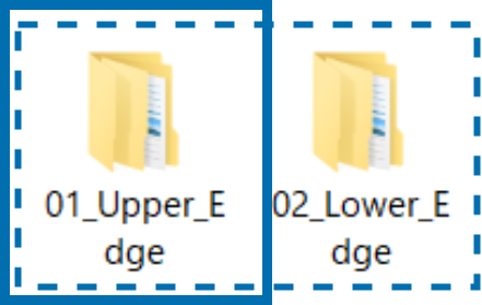
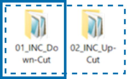
XEBEC Path data is stored in sperate folders as shown below.
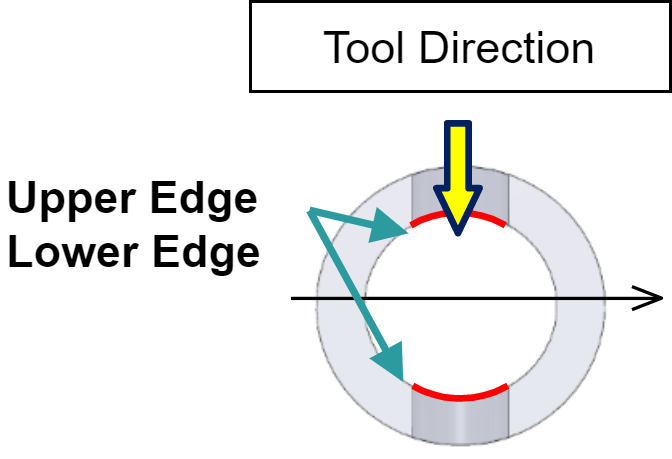
| ■First Folder Level Contains folders for each target edge (Upper Edge / Lower Edge) to be deburred |
|
▼ |
|
| ■Second Folder Level Contains folders for following data sets
|
|
▼ |
|
| ■Third Folder Level Contains a set of five XEBEC Paths in .txt format, each corresponding to a specific deburring amount (edge break length) |
|
▼ |
|
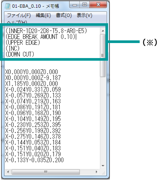
■Text File (.txt) Specifications are listed at the top in parentheses ( ) |
|
 |
For XEBEC Path for XZC-axis lathes, the data set exist only for the Upper Edge of both Outer and Inner Diameter cross holes. In that case, a total of 10 text files is provided. |
Data Example
For example, a total of 20 text files are included for an Inner Diameter cross hole.
- First Folder Level (2 Folders)
Upper Edge and Lower Edge - Second Folder Level (2 Folders)
Incremental (INC) Up Cut / Down Cut - Third Folder Level (5 Text Files)
Each text file corresponds to a specific deburring amount (edge break length)
Examples of XEBEC Path Specifications
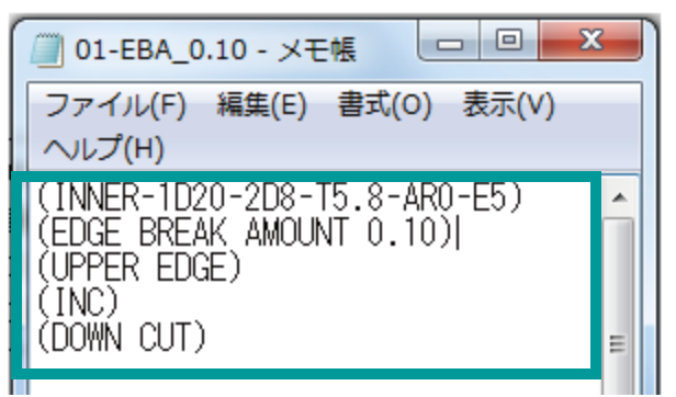
Example: On-center/Off-center Cross Hole XZY Machine Axis
(INNER-1D20-2D10-T5.8-E5);
(EDGE BREAK AMOUNT 0.10);
(DIAMETR);
(UPPER EDGE);
(INC) ;
(DOWN CUT);
Example: Orthogonal Cross Hole XZC Machine Axis
(INNER-1D20-2D10-T5.8-E5);
(EDGE BREAK AMOUNT 0.10);
(DIAMETR);
(UPPER EDGE);
(INC) ;
(DOWN CUT);
Specifications |
Descriptions |
(INNER-1D20-2D10-T5.8-E5); |
INNER: Inner Edge [ OUTER: Outer Edge] |
(EDGE BREAK AMOUNT 0.10); |
Deburring Amount 0.10mm |
| (DIAMETR); | X-axis Controller Mode: Diameter [ RADIUS: Radius] |
(UPPER EDGE); |
Upper Edge [ LOWER: Lower Edge] |
(INC) ; |
Positioning Format: Incremental |
(DOWN CUT); |
Down Cut Machining [ UP CUT: Up Cut Machining ] |
 |
Specifications in the table above are applicable to XEBEC Path for XZY lathes and XZC lathes |
