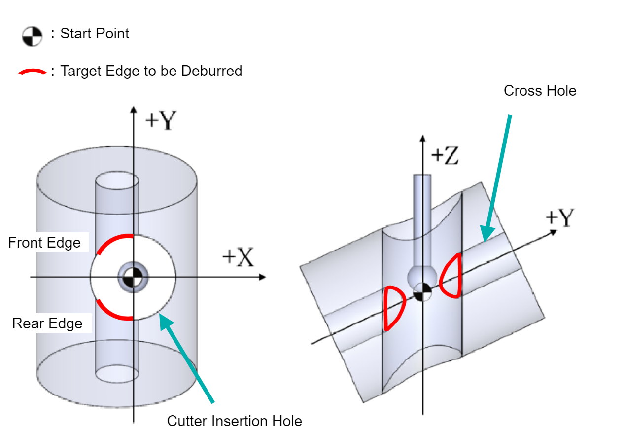
Type N: Angled Cross Hole Inner Diamater (Off-center) - (Cutter Insertion Hole > Cross Hole)
The Start Point is at the center of the Cutter Insertion Hole in the XY plane. Along the Z-axis, it is it is at the intersection of the axes of Cutter Insertion Hole and the Cross Hole.
XEBEC Path for absolute positioning (ABS) is generated with the Start Point position as the machine zero point (X0Y0Z0).
Example: Angled Cross Hole (Off-Center) - Inner Diameter
 |
|
XEBEC Path Specifications
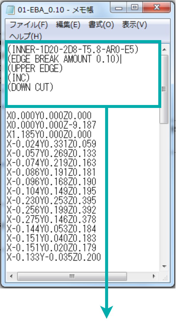
Specifications are indicated at the top of the text file in parentheses ( )
Specifications |
Descriptions |
| (INNER-1D8-2D20-T5.8-AR0-E4.5-AA60.) | INNER: Inner Edge 1D20: Cross Hole Diameter Φ8mm 2D10: Cutter Insertion Hole Diameter Φ20mm T5.8: Cutter Diameter Φ5.8mm AR0: Cross Hole Orientation Angle 0° AA60: Inclination Angle +60° E4.5: Offset +4.5mm from the Cross Hole Axis |
| (EDGE BREAK AMOUNT 0.10) | Deburring Amount 0.10mm |
| (FRONT EDGE) | Front Edge [ REAR EDGE: Rear Edge ] |
| (INC) | Positioning Format: Incremental [ ABS: Absolute ] |
| (DOWN CUT) | Down Cut Machining [ UP CUT: Up Cut Machining ] |