Type F: Angled Surface Hole
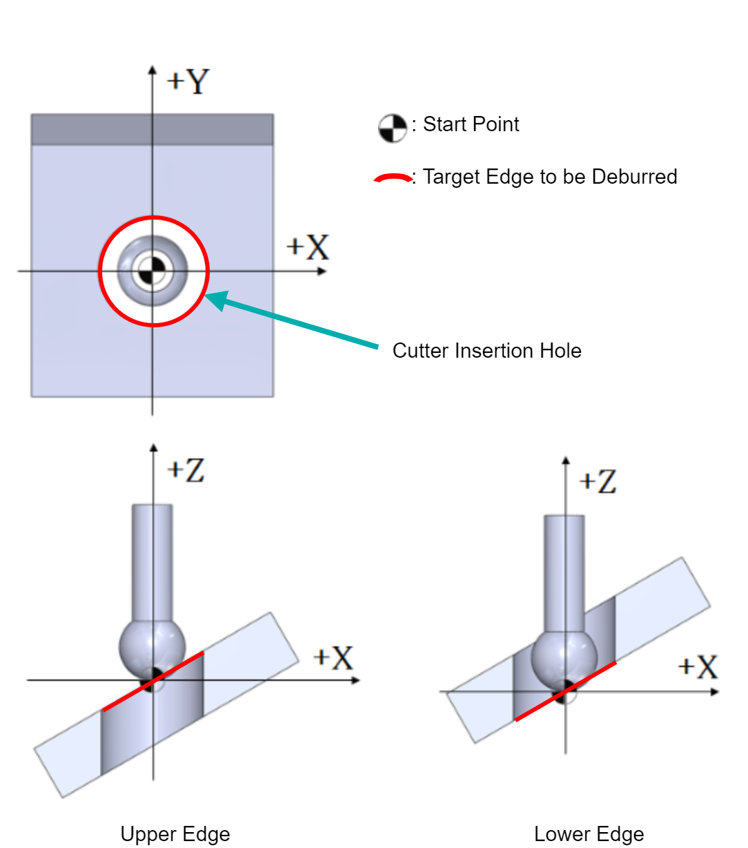
The Start Point is at the center of the Cutter Insertion Hole in the XY plane.
Along the Z-axis, it is at the intersection of the Cutter Insertion Hole axis and the upper/lower angled surface.
XEBEC Deburring Tool Path for absolute positioning (ABS) is generated with the Start Point position as the machine zero point (X0Y0Z0).
Example: Tapped Angled Surface Hole
 |
Machining Parameters To minimize the risk of secondary burrs, keep the tool projection length as short as possible. In case secondary burrs form, reduce the feed rate to 50% of the standard machining parameter and work with the smallest deburring amount (edge break length). |
XEBEC Deburring Tool Path Specifications
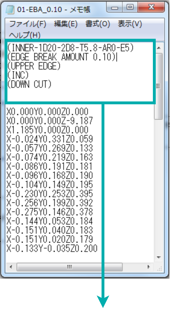
Specifications are indicated at the top of the text file in parentheses ( )
Specifications |
Descriptions |
|---|---|
| (2D10.-T5.8-AR0-AA60.) | 2D10: Cutter Insertion Hole 2D Diameter Φ10mm T5.8: Cutter Diameter Φ5.8mm AR0: Cross Hole Orientation Angle 0° AA60: Inclination Angle +60° |
| (EDGE BREAK AMOUNT 0.30) | Deburring Amount 0.30mm |
| (BACK EDGE) | The Edge at the Backside [FRONT: The Edge at the Front Side] |
| (INC) | Positioning Format: Incremental [ABS: Absolute] |
| (DOWN CUT) | Down Cut Machining [UP CUT: Up Cut Machining] |