Target Edges to Deburr
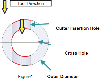
The red lines in Figures 1 and 2 are examples of the edges to be deburred.
 |
Depending on the configuration of cross holes, it may not be possible to create a Deburring Tool Path. |
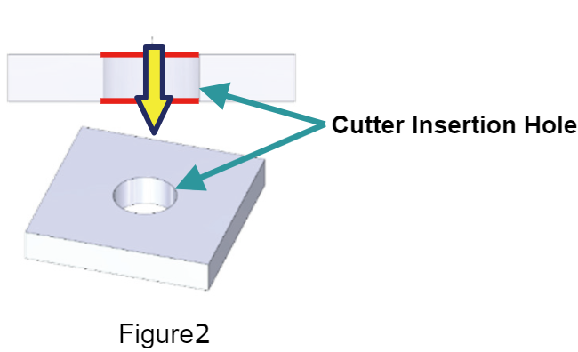
The red lines in Figures 1 and 2 are examples of the edges to be deburred.
|
Depending on the configuration of cross holes, it may not be possible to create a Deburring Tool Path. |